How to Perform Power Transformer Testing?
Power transformer testing is the practical evidence behind a transformer’s safety, reliability, and expected service life. It begins before energized operation, when engineers inspect bushings, radiators, conservators, tap changers, grounding connections, and oil leaks. Small details matter. A loose terminal can distort results. Moisture can quietly weaken insulation. According to transformer specialist S. V. Kulkarni, “The life of a transformer is the life of its insulation.” This statement explains why testing must examine more than visible damage.
A professional test program combines several methods. Technicians may measure winding resistance, turns ratio, insulation resistance, power factor, and excitation current. They may also perform frequency response analysis and dissolved gas analysis on the insulating oil. Each test reveals a different part of the transformer’s condition. A high moisture level may appear in oil results, while abnormal winding resistance may suggest a connection problem. Field experience remains essential. Instruments can report numbers, but engineers must interpret those numbers against factory data, temperature, previous records, and applicable standards.
Testing is not a guarantee.
Results can be affected by temperature, grounding, instrument accuracy, or poor preparation. That weakness deserves attention. A clean report does not prove that future failures are impossible. Instead, power transformer testing creates a defensible condition record and supports better maintenance decisions. This guide explains the major procedures, required precautions, typical findings, and practical limitations. It also considers what test results may mean in real substations, where noise, weather, restricted access, and aging equipment complicate the work. Reliable conclusions come from careful preparation, qualified personnel, repeatable methods, and honest review of uncertain evidence.
Define the Purpose and Scope of Power Transformer Testing
Before testing a power transformer, define the decision it must support. Is the unit being accepted after manufacture, commissioned after installation, or assessed after a fault? Each purpose requires a different scope. A commissioning plan may include insulation resistance, winding resistance, turns-ratio verification, excitation current, power-factor testing, and oil sampling. IEEE C57.12.90 describes recognized methods for several routine and design-related electrical tests. The test team should record temperature, humidity, tap position, oil condition, and previous results. Small details matter.
Maintenance testing should focus on changing condition, not collecting numbers without context. Dissolved gas analysis can indicate overheating, arcing, or cellulose degradation, while frequency-response testing can reveal winding movement after a short circuit. CIGRE Technical Brochure 642 examined 964 major transformer failures and identified windings, insulation, and bushings among important failure areas. That evidence supports a targeted scope around mechanical integrity and insulation health. Yet one test rarely proves safety. It is only one piece.
The scope should define test limits, instruments, personnel, isolation procedures, and actions for abnormal results. Compare results with factory records whenever possible. A baseline is valuable. A perfect baseline is not always available. Field conditions may distort readings, and older records may be incomplete. Testing should therefore combine measured trends, visual inspection, operating history, and engineering judgment. The final report needs raw values, corrected values, deviations, and clear recommendations, rather than a simple pass-or-fail label.
Perform Visual, Mechanical, and Electrical Condition Checks
How to Perform Power Transformer Testing?
A reliable transformer test begins with visual, mechanical, and electrical checks. CIGRE Technical Brochure 642 examined 964 major transformer failures across 47 countries. Its findings highlight windings, bushings, and tap changers as frequent failure points. That evidence supports a simple rule: inspect the physical condition before energizing complex test equipment.
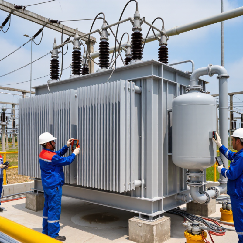
Start with the enclosure, oil leaks, corrosion, cracked porcelain, and unusual staining. Check the oil level and silica gel breather condition. Look for loose hardware, damaged cables, and blocked cooling paths. Mechanical checks should include tap-changer operation, grounding connections, valves, and radiator fans. A small leak near a flange can become a serious insulation problem. It is easy to miss.
Electrical testing should follow the equipment history and applicable IEEE or IEC guidance. Measure insulation resistance, winding resistance, turns ratio, and power factor. Compare results with previous records, not only factory limits. Sudden changes often matter more than one poor reading. Sweep frequency response analysis can reveal winding movement after transport or short-circuit stress. Dissolved gas analysis may identify overheating, arcing, or paper degradation, but interpretation requires trained judgment. Field conditions are rarely perfect. Temperature, moisture, instrument leads, and incomplete records can distort results. A test report should state these limitations clearly, including the readings that need repeating.
Conduct Insulation, Ratio, Winding Resistance, and Oil Tests
How to Perform Power Transformer Testing?
Conduct Insulation, Ratio, Winding Resistance, and Oil Tests
Power transformer testing confirms whether a unit can operate safely under load. Testing should begin with an isolated transformer, verified grounding, and a controlled work area. Qualified technicians must follow site procedures and applicable electrical standards. A careful test plan prevents avoidable damage.
Insulation resistance testing uses a suitable insulation tester between windings and ground. Record temperature, humidity, test voltage, and stabilization time. Dry, clean bushings usually produce more dependable readings. Polarization index testing can reveal moisture or aging inside the insulation system. However, one low result does not always prove failure. Surface contamination may distort the measurement.
The transformer ratio test compares measured ratios with the nameplate values across every tap position. Small deviations can indicate tap changer problems or incorrect connections. Winding resistance testing detects loose joints, damaged conductors, and poor contacts. The readings must be temperature-corrected before comparison. A rushed connection can create a false fault.
Oil testing examines dielectric strength, moisture, acidity, and dissolved gases. Sampling requires clean containers and careful handling. The sample should represent the oil, not sediment from the drain valve. Dissolved gas results can suggest overheating, arcing, or insulation breakdown. Interpretation needs operating history and previous test records. I have seen teams focus on a single number and miss the trend. Repeating a questionable test is often wiser than forcing a quick decision.
How to Perform Power Transformer Testing? - Conduct Insulation, Ratio, Winding Resistance, and Oil Tests
Illustrative test record for a three-phase oil-immersed transformer. Results and acceptance limits must be assessed against the transformer design, test method, temperature, and applicable standards.
| Test |
How It Is Performed |
Illustrative Data |
Assessment |
| Insulation resistance (IR) |
With the transformer isolated and safely discharged, apply the specified DC test voltage between windings and ground. Record readings at 1 minute and, when required, 10 minutes. |
HV-to-ground at 5 kV DC: 1-minute reading 2.4 GΩ; 10-minute reading 5.3 GΩ. |
Record winding and oil temperature. Compare with previous results and the applicable test guidance; there is no single universal IR limit for all transformers. |
| Polarization index (PI) |
Calculate the ratio of the 10-minute IR reading to the 1-minute IR reading using the same test connection and voltage. |
5.3 GΩ ÷ 2.4 GΩ = 2.21. |
A rising IR trend can indicate favorable insulation behavior, but PI interpretation depends on insulation type, temperature, and test conditions. |
| Turns ratio and tap position |
Use a transformer turns-ratio tester on each phase and specified tap. Compare measured ratios with the nameplate or design values. |
Example nameplate ratio: 13,800:480 V. Measured ratios: A 28.71, B 28.69, C 28.72; nominal ratio: 28.75. |
Example maximum deviation is approximately 0.21%. Confirm against the transformer specification and applicable standard; also verify phase relationship and tap position. |
| Winding resistance |
Measure each phase with a winding-resistance meter using a stable DC current. Allow readings to stabilize, record winding temperature, and safely discharge the windings afterward. |
HV winding at 25°C: A 1.842 Ω, B 1.850 Ω, C 1.846 Ω. |
Maximum phase spread is approximately 0.43% of the average. Compare temperature-corrected readings between phases, taps, and historical records. |
| Oil breakdown voltage (BDV) |
Take a clean, representative oil sample and test it in a calibrated dielectric-strength tester using the prescribed electrode arrangement and method. |
Illustrative average: 68 kV across a 2.5 mm gap, based on six breakdown tests. |
Interpret only with the specified sampling and test method; BDV limits vary with equipment class, oil condition, and applicable standard. |
| Oil moisture content |
Measure water content in a properly sealed oil sample, commonly by Karl Fischer titration, and record the oil temperature. |
Illustrative result: 12 mg/kg (ppm) at 25°C. |
Assess in context with transformer voltage class, oil temperature, insulation condition, and relevant limits. |
| Oil acidity (neutralization value) |
Analyze a representative oil sample in a laboratory using a recognized acidity test method. |
Illustrative result: 0.03 mg KOH/g. |
Trend results over time and evaluate alongside other oil tests; acceptance depends on the maintenance plan and applicable criteria. |
Safety: Perform testing only with suitable training, isolation, grounding, calibrated equipment, and approved procedures. Discharge and ground windings after DC tests before handling connections.
Interpret Test Results and Document Required Maintenance
Power transformer testing only becomes useful when results guide maintenance decisions. CIGRE Technical Brochure 642 reviewed 964 transformer failures and identified windings, bushings, and tap changers as recurring failure locations. These findings support targeted testing rather than routine box-ticking. Trends matter.
Interpret dissolved gas analysis under IEC 60599 and IEEE C57.104 guidance. Compare gas concentrations with previous samples, loading history, oil temperature, and sampling quality. A rising hydrogen or acetylene level deserves engineering review, even when one result remains below an alarm limit. One sample is weak evidence. Insulation resistance, winding resistance, turns ratio, and power factor should also be compared with factory or commissioning records. Temperature correction is easy to overlook.
Maintenance documentation must show the measurement, test method, instrument identification, calibration status, ambient conditions, and technician’s judgement. Record exact values, not vague phrases such as “acceptable” or “normal.” Link each abnormal result to an action, deadline, and responsible person. For example, a drifting turns ratio may require tap-changer inspection, while increasing moisture may justify oil processing and a follow-up test. CIGRE reliability data supports this traceable approach. Still, interpretation is not perfect. Conflicting results should trigger repeat testing and independent review, rather than forced certainty. Photographs of terminals, oil bottles, and connection conditions can preserve details that numbers miss.
How to Perform Power Transformer Testing? — Interpret Test Results and Document Required Maintenance
Illustrative transformer turns-ratio test results. The bars show the absolute percentage deviation from the nameplate ratio for each phase; the dashed line marks a commonly used 0.5% screening tolerance. Confirm acceptance criteria with the transformer manufacturer and applicable standards.
These example readings are within the screening tolerance. Record the test date, tap position, test instrument and calibration status, test connections, measured ratios, ambient conditions, and comparison criteria. If readings exceed the applicable limit or differ unexpectedly between phases, verify connections and tap-changer position, repeat the test, and document investigation and corrective maintenance.