Choosing the right dry transformer is not simply a matter of comparing price, capacity, and delivery time. The decision affects safety, operating costs, maintenance access, and power quality for many years. In real projects, a transformer may sit above a production line, inside a hospital electrical room, or beside sensitive data equipment. Its environment changes everything.
The U.S. Department of Energy’s Distribution Transformers Technical Support Document estimates that distribution transformers account for roughly 2.5% of total U.S. electricity consumption. That figure shows why efficiency deserves serious attention, even when no-load losses seem small. Meanwhile, the International Energy Agency’s Electricity 2024 report projects global electricity demand to grow by an average of 3.4% annually from 2024 through 2026. More demand places greater pressure on dependable distribution equipment. A dry transformer can support this transition, but only when its insulation system, cooling method, voltage ratio, and installation conditions are properly matched.
Standards provide a useful foundation. IEC 60076-11 addresses dry-type transformers, while IEEE C57.12.01 covers general requirements for ventilated dry-type transformers. Yet compliance alone does not guarantee a practical selection. A specification may look complete while overlooking altitude, dust, humidity, harmonics, or future load growth. That is where engineering judgment matters. The following seven tips focus on those real-world details, helping buyers compare designs with greater confidence. Some choices remain imperfect. A lower purchase price can create higher lifetime costs, and a compact enclosure can restrict cooling and inspection. Careful evaluation is still the safer investment.
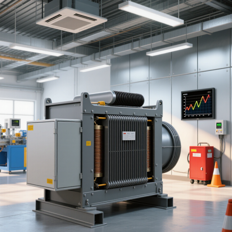
7 Tips to Choose the Right Dry Transformer
Start by defining the application clearly. A transformer serving an office tower has different duty cycles from one feeding a welding line or a solar installation. Record indoor or outdoor location, altitude, ambient temperature, harmonic content, cooling conditions, and required noise limits. Then confirm primary and secondary voltage, frequency, phase arrangement, grounding method, and insulation level. Small misunderstandings here can create expensive redesigns. Keep the specification practical. Overengineering is not free.
Estimate present load by separating motors, lighting, power electronics, and future equipment. Check starting current, continuous demand, diversity, and expected operating hours. The IEA’s Electricity 2024 report projects global electricity demand to grow by an average 3.3% annually from 2024 to 2026. That trend makes future capacity worth testing, not guessing. Add a 10–20% design margin after realistic load calculations. It should cover credible growth and uncertainty, not hide poor measurements.
Seven checks matter: application, voltage, load profile, harmonics, environment, protection, and growth margin. Select kVA from measured demand, not connected nameplate totals alone. Consider K-factor requirements where nonlinear loads are significant. Review short-circuit withstand, impedance, temperature rise, and coordination with protective devices. The U.S. Department of Energy’s distribution-transformer rulemaking documents emphasize transformer efficiency and lifecycle energy use, showing why no-load losses deserve attention. A lower purchase price may perform badly over decades. I have seen projects oversize transformers “for safety,” then operate them lightly for years. That choice needs reflection. Validate assumptions with site data, thermal calculations, and an independent engineering review before ordering.
| No. | Selection Tip | Key Data to Define | Practical Guidance | Typical Design Check | Example Specification |
|---|---|---|---|---|---|
| 1 | Define the application | Facility type, duty cycle, installation location, criticality, and operating environment | Identify whether the transformer serves lighting, HVAC, motor loads, data equipment, industrial machinery, or mixed loads. Continuous and highly critical loads may require additional monitoring or redundancy. | Check indoor or outdoor installation, ventilation, access, fire requirements, noise limits, and maintenance conditions. | Indoor commercial building; continuous operation; low-maintenance installation; ventilated electrical room. |
| 2 | Match primary and secondary voltage | System voltage, frequency, phase arrangement, grounding method, and tap requirements | Select a transformer with a primary rating compatible with the supply and a secondary rating compatible with the distribution system. Confirm line-to-line and line-to-neutral requirements. | Verify voltage tolerance, 50/60 Hz frequency, delta or wye connection, neutral availability, and required impedance. | Primary: 13.8 kV; secondary: 480Y/277 V; 60 Hz; three-phase; grounded secondary neutral. |
| 3 | Calculate the present load | Connected load, demand load, power factor, motor starting current, and load diversity | Use measured demand where available. For new installations, calculate kVA from real power and power factor rather than adding nameplate ratings without diversity analysis. | For three-phase systems: kVA = √3 × line voltage × line current ÷ 1,000. For single-phase systems: kVA = voltage × current ÷ 1,000. | Estimated maximum demand: 360 kVA at 0.90 power factor, with occasional motor starting events. |
| 4 | Allow for future load growth | Expected expansion, additional equipment, electrification plans, and forecast operating demand | Apply a documented 10–20% growth margin when the future load is reasonably predictable. Avoid excessive oversizing because very light loading can increase initial cost and reduce operating efficiency. | Future design load = present maximum demand × 1.10 to 1.20. Recheck voltage drop, protection settings, and available fault current. | 360 kVA × 1.15 = 414 kVA; select the next suitable standard rating after engineering review. |
| 5 | Check cooling and environmental conditions | Ambient temperature, altitude, enclosure rating, humidity, dust, corrosive agents, and ventilation | Dry transformers depend on air circulation to dissipate heat. Restricted airflow, high ambient temperature, or high altitude may require derating or additional cooling provisions. | Confirm manufacturer temperature-rise data and correction factors for the actual site. Keep required clearances around ventilation openings. | Indoor site; maximum ambient temperature: 40°C; installation altitude below 1,000 m; natural-air cooling. |
| 6 | Evaluate harmonics and special loads | Variable-frequency drives, rectifiers, UPS systems, switch-mode power supplies, computers, and nonlinear loads | Harmonic currents can increase winding losses and heating. A standard kVA calculation may be insufficient when nonlinear loads represent a significant portion of the demand. | Review total harmonic distortion, neutral current, crest factor, and any required K-factor or harmonic-mitigation design with a qualified engineer. | Approximately 35% nonlinear load; evaluate harmonic heating and neutral conductor loading before final selection. |
| 7 | Verify safety, protection, and compliance | Insulation level, short-circuit withstand, impedance, sound level, fire performance, enclosure, and applicable standards | Coordinate primary and secondary protection with the transformer impedance and available fault current. Confirm the installation complies with local electrical and fire regulations. | Review short-circuit calculations, protective-device coordination, grounding and bonding, working clearances, temperature monitoring, and acceptance-test requirements. | Short-circuit withstand suitable for the calculated fault level; temperature sensors and alarm contacts included where required by the design. |