Global buyers need reliable transformer core testing before approving materials, suppliers, or finished units. Core quality directly affects no-load loss, heating, noise, efficiency, and service life. A small measurement error can become a costly field problem.
The International Energy Agency’s Electricity Grids and Secure Energy Transitions report estimates that annual grid investment must rise above USD 600 billion by 2030. It also highlights equipment bottlenecks and longer procurement cycles. The U.S. Department of Energy’s Electric Grid Supply Chain Review reported that large power transformers can require lead times of up to 36 months. These pressures make dependable factory testing essential, not optional.
This guide examines Epstein frame testing, single-sheet testing, loss measurement, magnetic flux checks, and interlaminar insulation verification. It also considers visual inspection, dimensional control, sampling plans, and calibration records. IEC 60404-2 provides key methods for measuring magnetic properties of electrical steel. IEC 60076 supports broader transformer performance verification. Experienced buyers should request raw test data, test conditions, instrument calibration dates, and acceptance limits. A polished certificate is not enough.
No single test is enough. That assumption deserves scrutiny. Results may change with cutting stress, burrs, stacking pressure, temperature, or operator technique. Buyers should compare supplier data with independent laboratory results when project risk is high. The best approach combines standardized measurements with practical factory experience. It should also leave room for review when results appear unusually perfect.
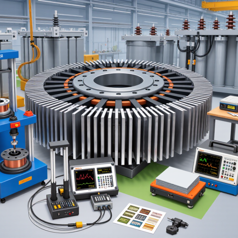
Global buyers should treat transformer core testing as a documented acceptance process, not a factory formality. IEC 60404-2 defines magnetic test methods for electrical steel, including specific total loss and magnetic polarization measurements. During inspection, buyers should request Epstein-frame or single-sheet tester results, steel grade certificates, coating data, and sampling records. Core loss should be checked at the promised flux density and frequency. Small changes matter.
The U.S. Department of Energy’s technical analysis estimated that distribution transformers could save about 3.6 quadrillion BTUs over 30 years through efficiency improvements. That figure makes no-load loss testing commercially important. Buyers should compare measured watts per kilogram with guaranteed values, then verify stacking factor, burr height, joint design, and clamping pressure. Infrared inspection can reveal abnormal local heating after assembly. It is useful, but not enough alone.
Factory acceptance should also follow the applicable transformer standard, such as IEC 60076-1 or IEEE C57.12.90. Require calibrated instruments, traceable test dates, raw data, and an agreed tolerance before production begins. A passed report is not proof of perfect performance. Sampling may miss damaged corners or uneven laminations. I have seen specifications focus heavily on headline efficiency while ignoring transport vibration and core noise. That deserves a second look. Supplier audits, witness testing, and independent verification reduce uncertainty for global purchasing teams.
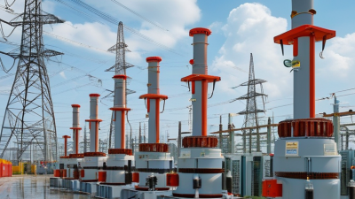
Transformer core inspection should begin with the steel certificate, not the finished assembly. Verify grade, coating condition, rolling direction, thickness, and magnetic-loss values against the purchase specification. IEC 60404-8-7 defines requirements for grain-oriented electrical steel, while IEC 60404-3 describes Epstein-frame testing. These references support comparable results between laboratories.
A practical incoming test uses an Epstein frame or single-sheet tester. Measure specific total loss, magnetic polarization, and permeability at the declared frequency and flux density. Record temperature and specimen direction. Small errors matter. A 0.23 mm sheet can fail when coating damage increases eddy-current loss. DOE’s 2024 Distribution Transformers Final Rule estimates energy savings of 3.6 quadrillion Btu over 30 years. Core-loss control directly supports that efficiency target.
Dimensional inspection needs equal discipline. Check lamination thickness with a calibrated micrometer at several points. Measure leg width, window size, mitre angle, stacking height, and burr height. Inspect five to ten laminations from each production lot, then increase sampling after a failure. A narrow window can restrict winding clearance. Excessive burrs may damage insulation. Measure the assembled stack again, because pressure can change its height. A clean certificate is not proof. I have seen excellent steel paired with poor stacking control. That mistake remains easy to miss. Keep photographs, raw readings, calibration dates, and lot numbers with every inspection record.
Electrical-steel sheet thickness is a key dimensional control point in transformer core manufacturing. The chart shows representative nominal thicknesses commonly specified for electrical steel used in transformer cores. Buyers should verify the actual thickness, thickness tolerance, magnetic properties, surface insulation, burr height, core dimensions, and stacking factor against the applicable material and product standards.
Recommended verification methods include micrometer measurement for sheet thickness, caliper or coordinate-measuring inspection for core dimensions, burr-height measurement after cutting, Epstein-frame testing for magnetic loss and permeability, and stacking-factor measurement for the assembled core. Applicable requirements should be confirmed using the relevant IEC or ASTM material and test standards.
Magnetic performance testing reveals whether a transformer core can deliver stable efficiency in service. Global buyers should request measured data, not only catalog values.
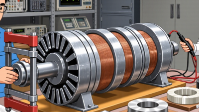
Core loss is commonly tested with an Epstein frame or a ring specimen. The method should match the material grade and intended operating frequency.
The laboratory applies a controlled sinusoidal flux density, often at 50 or 60 Hz. It records watts per kilogram, permeability, and excitation current. A B-H curve shows how easily the core magnetizes and where saturation begins. Small differences matter. A core with higher loss may run hotter inside a sealed transformer. That heat can shorten insulation life.
Magnetostriction testing adds another practical view. It measures dimensional changes during magnetization, which can create audible humming. Inspectors should check samples after cutting, stacking, and clamping.
Mechanical stress can raise loss and alter permeability. Temperature testing is also useful, especially for transformers operating outdoors or under heavy loads. Keep the setup consistent.
Repeatability deserves attention. A rushed fixture can distort results. No test is flawless. Buyers should compare multiple samples, review calibration records, and confirm the sampling plan.
Ask whether measurements cover the rolling direction and transverse direction. Those results may differ noticeably.
A clear report should state frequency, flux density, specimen dimensions, temperature, uncertainty, and acceptance limits. That detail supports fair supplier comparisons and reduces costly surprises after shipment.
Transformer Core Testing Methods for Global Buyers
Loss testing measures how much energy the core wastes during operation. Engineers usually apply controlled voltage and frequency, then record no-load loss and excitation current. Calibrated power analyzers are essential because small measurement errors can affect purchase decisions. Testing should match the buyer’s required operating frequency and voltage. A core may pass at one condition but perform poorly under another. That detail matters.
Noise testing examines audible vibration from magnetostriction and loose core clamping. Technicians measure sound pressure at defined distances and locations. The test area should have stable background noise and limited reflected sound. They should also inspect joints, clamps, and winding support structures. A quiet result is not always reliable if the room is poorly controlled. This is where experienced judgment matters.
Thermal testing monitors temperature rise during sustained operation. Sensors should cover the core surface, joints, frame, and nearby insulation. Infrared cameras can reveal hot spots, but contact sensors provide stronger verification. Tips: Request raw loss, noise, and temperature records, not only pass-or-fail sheets. Confirm instrument calibration dates and test conditions. Ask whether tests were repeated after transport or assembly. A practical concern remains: temperature readings can drift when sensors move slightly. Buyers should document fixture positions carefully and review unusual results before approval.
| Testing Area | Key Measurement | Typical Procedure | Main Standard Reference | Important Test Conditions | Buyer Review Points |
|---|---|---|---|---|---|
| No-Load Loss | Core loss at rated voltage and frequency, normally reported in watts or kilowatts | Apply rated-frequency sinusoidal voltage to the energized winding while the other windings remain open. Measure input power after correcting for instrument and winding losses where required. | IEC 60076-1; IEEE C57.12.90 | Rated voltage, rated frequency, correct waveform, stable ambient temperature, and calibrated power analyzer | Compare the measured value with the guaranteed loss, purchase specification, and applicable tolerance. Confirm whether loss is stated at rated voltage or another declared test voltage. |
| Excitation Current | Magnetizing or no-load current as a percentage of rated current | During the no-load test, measure the RMS current drawn by the energized winding at the specified voltage and frequency. | IEC 60076-1; IEEE C57.12.90 | Correct connection polarity, stable supply frequency, and sufficient measurement accuracy for low current values | Review current symmetry between phases and investigate abnormal increases, which may indicate core-joint problems, excessive flux density, or winding connection errors. |
| Specific Core Loss | Core loss normalized by active core mass, commonly expressed as W/kg | Calculate the measured no-load loss divided by the verified mass of the active magnetic material, using the agreed calculation basis. | IEC 60404-2 for magnetic materials; IEC 60076-1 for transformer testing | Accurate core mass, defined material condition, specified induction level, and declared frequency | Do not compare W/kg values unless frequency, peak flux density, material grade, processing condition, and calculation method are identical. |
| Load Loss and Short-Circuit Loss | Winding I²R loss plus additional stray loss at specified current | Short-circuit one winding and circulate rated current through the other winding. Measure voltage, current, and input power, then correct the result to the specified reference temperature when required. | IEC 60076-1; IEEE C57.12.90 | Specified current, power factor, winding temperature, tap position, and reference temperature | Verify that the report separates no-load loss from load loss and clearly states the temperature correction method. |
| Audible Sound Level | A-weighted sound pressure level, reported in dB(A) | Operate the transformer at the specified voltage and frequency. Measure sound pressure at defined positions around the unit, subtract background noise according to the selected method, and calculate the average or declared maximum. | IEC 60076-10; IEEE C57.12.90 | Low-background test area, calibrated sound-level meter, defined microphone distance and height, and stable operating condition | Confirm the measurement distance, number of microphone positions, background correction, operating voltage, and whether cooling equipment was running. |
| Core Vibration and Mechanical Noise | Vibration acceleration or velocity, plus tonal noise components | Use accelerometers or vibration sensors on accessible tank, frame, or core-support locations while recording the operating sound spectrum and fundamental-frequency harmonics. | IEC 60076-10; project-specific vibration requirements | Consistent sensor locations, rated operating condition, secure mounting, and separation of fan or pump noise | Look for abnormal peaks, loose clamping, resonant structures, and changes from the baseline record rather than relying only on overall dB(A). |
| Temperature-Rise Test | Top-oil temperature rise, average winding temperature rise, and hot-spot temperature estimate or measurement | Run the transformer under the specified load and cooling mode until thermal equilibrium is reached. Record oil and ambient temperatures, then determine winding temperature by resistance measurement or approved direct sensors. | IEC 60076-2; IEC 60076-1; IEEE C57.12.90 | Rated load or agreed test load, declared cooling stage, stable ambient conditions, and thermal equilibrium | Check the cooling designation, ambient-temperature correction, measurement locations, stabilization criteria, and guaranteed temperature-rise limits. |
| Thermal Endurance of Insulation System | Insulation temperature capability and aging performance | For relevant dry-type transformer designs, expose insulation systems to defined thermal aging cycles and evaluate electrical and mechanical performance after aging. | IEC 60076-11; IEC 60085 for thermal classification | Specified insulation class, aging temperature, cycle duration, specimen construction, and post-aging tests | Confirm that the declared thermal class applies to the complete insulation system, not only to an individual material. |
| Infrared Thermal Scan | Surface temperature distribution and localized hot spots | Scan the tank, bushings, connections, radiators, and cooling equipment under stable load using a calibrated infrared camera. Compare similar phases and symmetrical components. | IEC 62446-3 principles for thermographic inspection; project maintenance procedures | Known emissivity, correct viewing angle, stable load, wind control, and recorded ambient conditions | Use thermography as a diagnostic tool, not as a replacement for a formal temperature-rise test. Investigate phase-to-phase temperature imbalance. |
| Core Insulation and Grounding Check | Insulation resistance or continuity between the core, clamps, and ground connection | Inspect the core grounding arrangement and perform the agreed insulation-resistance or continuity measurement with the transformer isolated and safely discharged. | IEC 60076-1; IEEE C57.12.90; applicable site-test procedures | Correct test voltage, safe isolation, dry condition, documented grounding configuration, and stable readings | Verify that the core is intentionally grounded at the designated point and that unintended multiple grounds have not been introduced. |
Global buyers should compare test conditions before comparing numbers. Core-loss results depend on flux density, frequency, waveform, temperature, and steel grade. A supplier reporting 0.85 W/kg may not match another supplier’s result at the same conditions. IEC 60404-2 defines measurement methods for magnetic materials, while IEC 60076-1 supports routine transformer verification. Ask for raw readings, specimen dimensions, correction factors, and calibration dates. Small details matter.
For complete transformers, review no-load loss, load loss, impedance, winding resistance, ratio, insulation resistance, and dielectric test results. IEEE C57.12.90 provides widely used test procedures for liquid-immersed transformers. Compare the same rated power, voltage, temperature reference, and tolerance limits. The U.S. Department of Energy estimated transformer losses at about 2.5% of national electricity use in its distribution-transformer analysis. That figure makes efficiency data commercially important, not decorative.
Supplier evaluation needs evidence beyond a polished report. Check whether the laboratory follows ISO/IEC 17025 and whether instruments have traceable calibration. Request serial-number photos, test-circuit details, failed-result records, and corrective-action reports. A witnessed test can reveal unstable connections or unusual noise. It is not perfect, though. Repeatability may still vary between laboratories, and one successful sample cannot prove long-term consistency. Buyers should compare test history across batches, not only the best certificate.