How to Choose the Right Transformer Core in 2026?

Choosing the right transformer core in 2026 is a practical engineering decision, not a materials contest. The core controls magnetic efficiency, heat generation, noise, size, and long-term reliability. A small choice in steel grade can affect every millimeter of a finished transformer.

Martin J. Heathcote, author of The J&P Transformer Book, wrote that “the transformer is a remarkably reliable piece of equipment when properly designed, manufactured, and maintained.” His point remains useful. A reliable transformer core begins with accurate operating data, not optimistic assumptions. Engineers should verify voltage, frequency, power rating, flux density, duty cycle, ambient temperature, and cooling conditions. Missing one detail can distort the whole selection.

Grain-oriented silicon steel often suits power-frequency transformers because it offers predictable losses and strong magnetic performance. Amorphous metal may reduce no-load losses, especially in continuously energized distribution units. Nanocrystalline materials can support compact, high-frequency designs, but cost and availability require closer review. No material wins everywhere.

Measure the real duty.

Core geometry matters, too. Stepped-lap joints, winding-window dimensions, clamping pressure, and insulation clearances influence performance. Manufacturing quality can defeat an excellent material. I have seen specifications focus heavily on core loss while overlooking joint workmanship and actual thermal paths. That approach needs reconsideration.

This guide examines how to compare transformer core materials in 2026. It connects laboratory data with field conditions, procurement risks, maintenance expectations, and total ownership cost. The best transformer core is not always the one with the lowest measured loss. It is the one that performs reliably within the complete system.

How to Choose the Right Transformer Core in 2026?

Transformer Core Fundamentals and Their Role in Power Conversion

Choosing the right transformer core in 2026 begins with understanding its fundamental job: guiding magnetic flux during power conversion. The core transfers energy between windings while limiting leakage, heat, and unwanted noise. Core material matters because frequency changes magnetic behavior. Ferrite suits many high-frequency converters, while laminated electrical steel remains practical at lower frequencies. Nanocrystalline materials can support compact designs, but cost and processing deserve scrutiny. A smaller core is not automatically better.

In a real design, I check switching frequency, voltage waveform, duty cycle, power level, and allowable temperature rise. I then estimate core loss from material curves and verify it with measured temperature. Keep the test setup honest. A winding that feels cool can hide hot spots near the air gap or connection points. The gap controls stored energy in inductive applications, but it also increases fringing fields and losses. For an isolation transformer, excessive gap may solve the wrong problem.

Mechanical fit also affects reliability. I inspect bobbin clearance, insulation distances, clamping pressure, and audible vibration under load. These details are easy to overlook. In 2026, simulation can narrow choices quickly, yet it cannot replace a prototype across light load, full load, and fault recovery. I once trusted a calculated loss value too much; the assembled unit ran warmer than expected. That mistake reinforced a useful habit: compare predicted performance with measured waveforms, thermal images, and repeated load tests before approving the core.
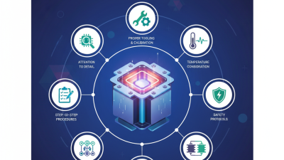

Define Electrical, Thermal, and Mechanical Design Requirements

How to Choose the Right Transformer Core in 2026?

Define Electrical, Thermal, and Mechanical Design Requirements

Core selection should begin with the electrical duty, not the catalog shape. Define voltage, frequency, power, waveform, and insulation requirements. Calculate peak flux density from the actual waveform, including switching spikes. A sinusoidal estimate can be dangerously optimistic. Leave margin.

Core loss depends on frequency, flux swing, material behavior, and operating temperature. Request measured loss data when possible, then verify it with your own test setup. I have seen calculations pass on paper while the prototype overheated near the winding window. Measure twice.

Thermal requirements need a clear temperature budget. Identify ambient temperature, allowable winding rise, cooling method, and enclosure restrictions. Natural convection may work on a bench, but restricted airflow changes everything. Check hot spots, not only average temperature. Use thermal sensors during representative loading.

Mechanical requirements deserve equal attention. Specify core dimensions, clamping pressure, vibration exposure, shock levels, mounting direction, and production tolerances. Excessive clamping can damage brittle core parts, while loose assemblies may create audible noise. Define creepage, clearance, and insulation placement early. They affect the core window and final size.

A reliable design review compares simulation, supplier data, prototype measurements, and applicable safety standards. Keep records for temperature, inductance, loss, noise, and dimensional variation. One overlooked tolerance can change the air gap and reduce performance. Recheck assumptions after every design revision.

This comparison uses representative material-level values to show the trade-off between electrical insulation, thermal headroom, and mechanical strength when selecting a transformer core. Scores are normalized to the highest value in each category; actual performance depends on grade, geometry, frequency, heat treatment, clamping, and operating conditions.

Representative reference values: MnZn ferrite: 100,000 Ω·cm resistivity, 220°C Curie temperature, 25 MPa tensile strength; nanocrystalline alloy: 0.0001 Ω·cm, 570°C, 600 MPa; silicon steel: 0.00005 Ω·cm, 745°C, 400 MPa.

Compare Core Materials, Shapes, and Magnetic Performance

How to Choose the Right Transformer Core in 2026?

Core material sets the starting point for efficiency, heat, and size. Grain-oriented silicon steel suits mains-frequency transformers with strong power handling. Ferrite is better for high-frequency designs because it reduces eddy-current loss. Amorphous and nanocrystalline materials can lower magnetic loss further, but they often cost more and require careful processing. I have seen a compact core run cooler than a larger one after engineers reduced its operating flux density. That result was not obvious from size alone.

Shape changes the practical design. EI cores are economical and easy to assemble. Toroidal cores can reduce leakage flux and audible vibration, but winding them takes more time. C-cores offer a useful balance between low loss and accessible construction. Compare effective magnetic path length, window area, air gaps, and cooling space. Magnetic performance depends on more than permeability. Check saturation flux density, core loss at the actual frequency, temperature behavior, and response to direct-current bias. Datasheet values can look impressive under conditions your circuit never reaches.

Tips: Measure the waveform, not only its nominal frequency. Include switching spikes and temperature rise. Leave a safety margin below saturation. A small thermal test often reveals a poor choice early. I would not trust a calculated core loss without checking winding resistance and assembly pressure. That judgment can be inconvenient, but real prototypes often disagree with clean calculations.

How to Choose the Right Transformer Core in 2026? - Compare Core Materials, Shapes, and Magnetic Performance

Core Material Typical Core Shape Recommended Frequency Typical Saturation Flux Density Typical Relative Permeability Core-Loss Tendency Main Advantages Main Limitations Typical Applications
Grain-Oriented Silicon Steel EI, UI, wound cut-core, three-leg core 50–400 Hz Approximately 1.7–2.0 T Approximately 1,000–10,000 Low at power frequency when properly laminated; rises with frequency and flux density High flux capability, mature manufacturing methods, economical for medium and high power Heavier than high-frequency materials; requires insulation between laminations Utility transformers, industrial transformers, line-frequency isolation transformers
Non-Oriented Silicon Steel EI, UI, distributed-gap and rotating magnetic assemblies 50–1,000 Hz Approximately 1.5–1.8 T Approximately 500–5,000 Moderate; generally higher than grain-oriented grades at the same operating point More uniform magnetic behavior in different directions; widely available Lower permeability and higher loss than grain-oriented steel for many transformer designs Small power transformers, reactors, inductors and magnetic components with multidirectional flux
MnZn Ferrite E, EE, EF, ETD, PQ, RM and toroidal 20 kHz–500 kHz Approximately 0.25–0.55 T Approximately 800–15,000 Very low at high frequency compared with laminated steel; strongly dependent on temperature and frequency High electrical resistivity, low eddy-current loss, compact size and good availability of standard shapes Low saturation flux density; brittle material; performance can change significantly with temperature Switch-mode power supplies, high-frequency transformers, gate-drive transformers and adapters
NiZn Ferrite Small E, cylindrical, bead and toroidal shapes 1 MHz–several hundred MHz Approximately 0.15–0.35 T Approximately 10–2,000 Very low at radio frequencies; selected grades are optimized for broadband operation Very high resistivity, low parasitic eddy-current loss and useful high-frequency impedance characteristics Lower permeability and lower flux capability than many MnZn ferrites; not usually preferred for power transfer at tens of kHz RF transformers, broadband transformers, common-mode chokes and high-frequency signal circuits
Amorphous Alloy Wound toroidal, wound cut-core and rectangular wound core 50 Hz–20 kHz Approximately 1.4–1.6 T Approximately 5,000–100,000 Very low at power frequency; typically lower than conventional silicon steel at comparable flux density Low hysteresis loss, high permeability and strong no-load efficiency potential More difficult processing, higher material cost and sensitivity to mechanical stress and sharp bending Energy-efficient distribution transformers, standby transformers and low-loss power magnetics
Nanocrystalline Alloy Wound toroidal, wound cut-core and common-mode choke core 1 kHz–200 kHz Approximately 1.0–1.3 T Approximately 20,000–150,000 Very low over a broad mid-frequency range; actual loss depends strongly on grade and flux waveform Extremely high permeability, high impedance per turn and excellent performance in compact magnetic filters Higher cost, lower saturation flux density than silicon steel and possible sensitivity to DC bias Common-mode chokes, high-efficiency transformers, current transformers and high-frequency power converters
Powdered Iron Toroidal, drum and molded cores with distributed air gap 10 kHz–500 kHz Approximately 0.7–1.5 T Approximately 10–300 Moderate to high; higher than ferrite in many high-flux applications but dependent on powder composition Distributed gap stores energy, handles DC bias well and reduces the need for a machined air gap Higher loss than ferrite at many switching frequencies; permeability is comparatively low Energy-storage inductors, DC chokes, boost inductors and high-current filter components
Design note: The values shown are typical engineering ranges rather than guaranteed specifications. Final core selection should be verified against the manufacturer’s material curves, operating temperature, waveform, duty cycle, DC bias, insulation system, thermal limits and allowable peak flux density.

Calculate Core Size, Losses, Temperature Rise, and Efficiency

How to Choose the Right Transformer Core in 2026?

Core selection starts with power, frequency, waveform, and allowable flux density. Estimate apparent power in VA, then calculate the effective core area from the required energy transfer. For a practical first estimate, use the relationship between VA, frequency, maximum flux density, window area, and winding utilization. Never trust a catalog size alone. A 500 VA transformer running at 50 Hz needs different dimensions from one operating at 100 kHz. Leave design margin for input variation, inrush, and imperfect winding placement.

Core losses come from hysteresis and eddy currents. Check the material’s loss data at your actual frequency, flux density, and temperature. Copper loss follows I²R, so longer windings or smaller conductors can raise heat quickly. I usually calculate core loss and winding loss separately, then verify both with a temperature test. A quiet prototype can still run hot inside an enclosed housing. Measure it.

Temperature rise depends on total watts, exposed surface area, airflow, and thermal resistance. Use ΔT = P × Rθ as an estimate, not a promise. Efficiency is calculated as output power divided by input power, including no-load and load losses. A design reaching 96% on paper may fall below that value after saturation, connection loss, or rising copper resistance. This is where engineering judgment matters. Add margin, record assumptions, and challenge them before production. The first calculation is rarely perfect.

Select the Best Core for Cost, Reliability, and 2026 Applications

How to Choose the Right Transformer Core in 2026?

Choosing the right transformer core in 2026 means matching materials to operating conditions. Start with frequency, power, waveform, insulation class, and enclosure temperature. For 50/60 Hz transformers, grain-oriented electrical steel remains practical and cost-aware. High-frequency converters usually need ferrite or advanced alloy cores. Nanocrystalline materials can reduce losses and size, but higher prices may complicate sourcing. No core wins everywhere. Measure twice.

Cost includes more than the purchase price. Calculate copper use, winding time, cooling hardware, scrap, and lifetime energy loss. A smaller core may look attractive until voltage spikes push it toward saturation. Check core-loss curves at the actual frequency, flux density, and temperature. Heat tells the truth. In 2026, data centers, solar inverters, battery systems, and fast-charging equipment require compact designs with stable thermal performance. Test worst-case loads, not only nominal conditions.

Reliability depends on the complete magnetic assembly. Inspect mating surfaces, clamping pressure, air gaps, varnish compatibility, vibration resistance, and insulation clearances. Request traceable material data and repeatable batch testing. Prototype measurements should include temperature rise, audible noise, standby loss, and waveform distortion. I would challenge optimistic simulations because real windings and imperfect cooling change results. A dependable core may cost more initially, yet it can reduce repairs and lost operating hours. Leave room for design error.