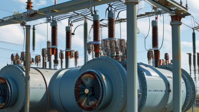
Improving transformer efficiency is not merely a matter of buying newer equipment. It requires careful measurement, realistic operating data, and decisions that fit each facility. A transformer may appear healthy while wasting energy through core losses, copper losses, heat, or poor power quality. That wasted electricity quietly increases operating costs every hour.
This guide examines practical ways to improve transformer efficiency in industrial plants, commercial buildings, and utility networks. Engineers can begin by recording load profiles, winding temperatures, voltage levels, and power-factor readings. A clamp meter, thermal camera, and properly configured monitoring system can reveal problems that routine inspections miss. Small details matter. Loose connections may create hot spots. Oversized units may operate inefficiently at light loads. Blocked ventilation can raise cooling demand and shorten insulation life.
Proven actions include selecting high-efficiency transformers, balancing three-phase loads, correcting power factor, and maintaining clean cooling paths. Predictive maintenance also helps identify abnormal noise, overheating, and insulation deterioration before failure occurs. Standards such as IEC 60076 and IEEE guidance can support safer engineering decisions, but local conditions still matter.
No upgrade is universally best. Replacing a transformer may reduce losses, yet manufacturing costs, installation downtime, and embodied energy deserve attention. Digital monitoring can improve visibility, but poorly calibrated sensors may create false confidence. That limitation is easy to overlook. A reliable energy plan compares measured savings with purchase, maintenance, and disposal costs. When teams review these results honestly, they can cut energy costs without sacrificing safety, reliability, or long-term performance.
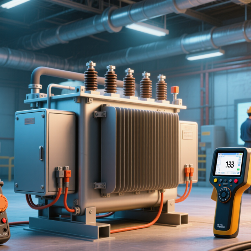
Transformer efficiency often looks impressive, yet small losses become costly during continuous operation. At 98–99.5% efficiency, the missing 0.5–2% becomes heat, not an abstract number. A 1,000 kVA transformer losing 1% wastes roughly 10 kW at rated load. That heat raises room temperature and can shorten insulation life. I have seen operators focus on nameplate efficiency while ignoring actual loading. That is an easy mistake.
I²R loss occurs in windings, bus connections, and sometimes loose terminations. Current creates heat through conductor resistance. Because current is squared, a small overload can increase copper loss sharply. Doubling current produces four times the I²R loss, assuming resistance remains stable. Temperature complicates this calculation because copper resistance rises when windings heat. Infrared scans, resistance tests, and load measurements provide useful evidence. They should be compared with design data, not treated as perfect proof.
Core losses continue even when the transformer supplies little or no load. Hysteresis loss comes from repeated magnetic reversal inside the steel core. Eddy-current loss develops when changing flux induces circulating currents in core material. These losses depend mainly on voltage, frequency, and core design. Poor voltage quality can increase heating beyond expected values. A practical review checks no-load power, loaded power, winding temperature, and ventilation. The 98–99.5% range is credible, but conditions matter. Real installations rarely behave like laboratory tests. That limitation deserves attention.
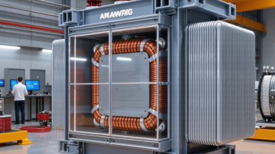
Transformer efficiency is not visible from one afternoon reading. Record current, voltage, power factor, and temperature at short intervals for a full day. This creates a loading profile that shows overnight demand, morning peaks, and lightly loaded periods. A transformer may appear efficient during peak hours, yet waste energy continuously when demand falls.
The U.S. Department of Energy states that no-load losses occur whenever a transformer remains energized, regardless of demand. Its distribution transformer efficiency analysis also identifies core losses as a persistent operating cost. The International Energy Agency estimates that electricity networks lose roughly 8% of generated power globally. Transformer losses form one part of that gap. Small losses become expensive when equipment operates for thousands of hours.
Compare measured input and output energy during each interval. Then separate no-load loss from load-related copper loss. A quiet warehouse may draw little power but still keep several transformers energized overnight. That is an easy detail to miss. Switching strategies, right-sizing, or consolidating lightly loaded units may reduce waste, but site safety and future demand must be checked carefully. The first measurement may be imperfect. Repeat it during different seasons, because one 24-hour profile cannot represent every operating condition.
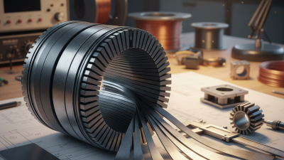
Transformer efficiency is often judged by load performance, yet no-load losses continue whenever the unit is energized. Amorphous core transformers address this hidden cost through a metal structure with very low magnetic loss. In suitable designs, they can reduce no-load losses by 60–70% compared with conventional grain-oriented silicon steel cores.
The difference becomes visible in a substation room. The transformer remains warm and lightly humming, even when little power reaches the equipment. With an amorphous core, less energy is converted into heat during standby operation. This matters for buildings, renewable energy systems, and distribution networks that remain energized around the clock. A practical audit should compare annual no-load kilowatt-hours, not only the purchase price.
The percentage is not guaranteed.
Core material is only one factor. Winding design, operating voltage, frequency, joint quality, and manufacturing tolerances also affect results. Engineers should request tested loss data under the actual operating conditions. Independent verification adds confidence. Poor installation can weaken expected savings.
There is also a trade-off. Amorphous metal can be more sensitive during handling, and its thinner core strips require careful assembly. I have found that projected savings sometimes look impressive before maintenance conditions are considered. A realistic evaluation includes transport, inspection, noise, service access, and the transformer’s expected energized hours. When these details align, cutting no-load losses can lower energy costs quietly, year after year.
Transformer efficiency starts with temperature control, not oversized cooling.
IEC 60076-7:2018 uses winding hot-spot temperature to assess insulation ageing. Under reference conditions, a 98°C hot spot represents normal ageing. Each additional 6–8°C can roughly halve insulation life. That small margin matters during summer peaks, blocked radiators, or repeated overloads. The U.S. Department of Energy’s 2024 technical analysis estimates that distribution transformers consume about 2.5% of U.S. electricity. Better thermal management can therefore reduce both losses and premature replacement.
Measure more than top-oil temperature. Install fibre-optic or validated indirect sensors near expected hot spots, then compare readings with IEC thermal models. Record load, ambient temperature, oil flow, and cooling-stage status.
A 5°C reduction may extend insulation life, but it can also increase fan energy and maintenance. The cheapest cooling setting is not always the best one. A perfect thermal model is unlikely; field data may disagree.
Review alarm thresholds after seasonal testing, not only during factory acceptance.
Tips: Set hot-spot alarms below the IEC limit, leaving a practical safety margin. Clean radiators and verify fan rotation before peak demand. Use staged cooling, rather than running every fan continuously. Check dissolved-gas and moisture results with temperature trends. DOE and IEC figures provide direction, but site conditions decide the final setting. Capture one year of operating data before approving permanent changes.
Validate upgrades against the U.S. Department of Energy’s 3.63-quadrillion-Btu savings projection. That figure gives manufacturers and facility owners a practical benchmark. It represents projected energy savings from improved distribution-transformer efficiency over the equipment’s operating life. The DOE’s technical analysis also links efficiency gains with lower operating costs and reduced grid demand. Numbers matter here.
Start with measured losses, not assumptions. Record no-load losses during energized periods and load losses during peak demand. A thermal camera can reveal hot connections, blocked ventilation, or uneven loading. The U.S. Energy Information Administration reports that transmission and distribution losses remain a meaningful part of delivered electricity. Even small improvements can compound across thousands of operating hours. Less heat helps.
Upgrade comparisons should include efficiency at actual loading conditions. A transformer performing well at 50% load may behave differently near its daily peak. The International Energy Agency continues to identify efficiency as a major tool for reducing electricity demand and emissions. Still, projected savings can disappoint when maintenance, voltage variation, or poor installation is ignored. That is the uncomfortable part. Validate results with twelve months of metered data, then compare avoided kilowatt-hours against the DOE benchmark. A spreadsheet is useful, but field conditions are messier.