What Are Transformer Designs and Which Type Is Best?
Transformer designs determine how electrical energy is transferred and how equipment performs under real operating conditions. The best choice depends on the job, not on a single universal ranking. A compact workshop unit may prioritize quiet operation and simple installation, while a substation transformer must handle substantial loads and changing conditions. Details matter. Core-type and shell-type designs differ in construction, while dry-type and liquid-immersed units suit different environments and maintenance plans. Isolation transformers and autotransformers also serve distinct purposes, so their differences should not be treated as interchangeable.
This guide compares common transformer designs and explains the practical trade-offs behind each type. It considers capacity, voltage, efficiency, cooling, installation space, operating environment, and maintenance needs. A nameplate can show ratings, but it cannot answer every site-specific question. Actual load patterns, ventilation, and access for servicing matter too. There is no perfect option. Even a clear comparison can oversimplify a complicated installation. For a real project, consult manufacturer documentation and have a qualified electrical professional confirm that the selected equipment meets the application’s requirements and relevant standards. The goal is not to label one design as best for everyone, but to identify which design fits the conditions safely and reliably.
What Defines a Transformer Design?
A transformer design is the coordinated arrangement of its magnetic core, windings, insulation, cooling system, and enclosure. It is more than a choice of shape. The core guides magnetic flux, while the winding ratio sets the voltage change. Laminated steel can limit eddy-current losses; conductor material and winding geometry affect resistance and heat. Insulation separates energized parts and must withstand electrical stress and operating temperature. Cooling matters, too. Oil-filled units transfer heat differently from dry-type units, which often rely on air and solid insulation.
Design choices follow the job. Engineers consider voltage, expected load, indoor or outdoor placement, available space, and maintenance access. A pole-mounted unit needs a compact, weather-resistant arrangement. An indoor unit may prioritize fire-safety requirements and ventilation. That distinction is easy to miss. Core losses occur whenever a transformer is energized; winding losses rise as load current increases. So a design that performs well at peak load may not be the most efficient under light, steady use.
Efficiency choices add up across many units. The U.S. Department of Energy’s 2013 distribution-transformer standards analysis projected 3.63 quadrillion Btu in cumulative energy savings over its 30-year analysis period. The estimate concerned efficiency standards, not one preferred construction type, but it shows why core and winding losses deserve careful attention. In practice, engineers compare measured losses, temperature rise, sound, footprint, and expected load patterns. The “best” design depends on those details—and load forecasts are not always right.
What Defines a Transformer Design?
Transformer designs are chosen for their application, operating frequency, power level, and required electrical isolation. The ranges below are illustrative typical operating-frequency ranges, not fixed limits.
Which type is best? A power transformer suits utility-frequency systems; an audio transformer is designed for signal transfer across audio frequencies; switching transformers work in high-frequency power converters; and RF transformers serve radio-frequency circuits. The best choice depends on the circuit’s frequency, power, and isolation requirements.
Key Components and Their Functions
A transformer’s parts work as a system, not as a checklist. The laminated steel core guides magnetic flux between the windings while limiting energy lost as heat. The primary winding receives electrical power; the secondary winding delivers it at a changed voltage. Their turns ratio sets the voltage relationship, but insulation and spacing also matter. In a core-type design, windings surround the core legs. In a shell-type design, the core surrounds more of the windings. Small detail, big effect.
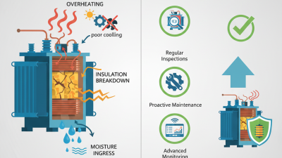
Insulation separates conductors and prevents short circuits under normal operating conditions. Dry-type units use solid insulation and rely on air for cooling. Oil-immersed units use insulating liquid to carry heat away from the core and coils. Radiators help release that heat. Bushings provide insulated paths for conductors to pass through the enclosure. A tap changer adjusts the winding connection to fine-tune output voltage; it does not replace correct system sizing. A loose or poorly maintained connection can still cause trouble.
The enclosure protects internal parts from dust, moisture, and accidental contact. Monitoring devices may track temperature or liquid level, giving technicians useful warning signs. Selection depends on load, installation space, ventilation, and maintenance access. I would not judge a design by efficiency figures alone; operating conditions can change the real result. For a specific installation, a qualified electrical professional should verify ratings and protection requirements.
Common Types of Transformer Designs
Transformer designs are commonly grouped by core arrangement, insulation, and cooling method. In a core-type transformer, windings surround the core limbs, making coils accessible for inspection. A shell-type design places more of the core around the windings, which can improve mechanical support under electrical stress. Neither layout wins in every application. Size, fault forces, heat, and repair access all matter.
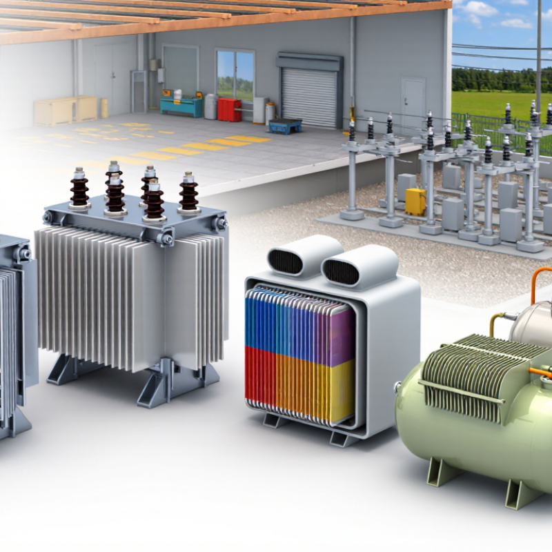
Insulation creates another practical distinction. Dry-type units use air and solid insulation, making them suitable for many indoor installations where liquid containment is undesirable. Liquid-immersed units transfer heat through insulating fluid and are common in outdoor distribution and higher-capacity service. Check the actual load profile, ambient temperature, ventilation, and maintenance plan; a category label alone is not enough. That detail gets missed.
Efficiency also depends on materials, geometry, and operating conditions, not just core or shell construction. The U.S. Department of Energy’s 2016 distribution-transformer standards rule estimated national energy savings of about 3.6 quadrillion Btu over 30 years. That is a projected impact across covered products, not a guarantee for any single installation. For selection, engineers compare no-load and load losses, sound limits, footprint, and expected duty cycle. A compact unit may fit a crowded electrical room, yet leave less room for cooling or service. The trade-off is real.
How Transformer Designs Differ in Performance
Transformer designs differ through their magnetic paths, winding layouts, insulation, and cooling methods. In a core-type design, windings sit around the core limbs, often making assembly and maintenance straightforward. A shell-type design surrounds more of the windings with core steel, which can improve mechanical support and reduce leakage flux. Neither arrangement is best for every installation. Load profile and fault forces matter.
Construction affects operating performance. Laminated steel cores reduce eddy-current losses, while grain orientation and joint quality influence magnetizing current and noise. Copper windings generally have lower resistance than equal-sized aluminum windings, but conductor choice also affects weight, cost, and heat management. Toroidal cores can be compact and quiet, though winding them may be labor-intensive. Their inrush current can also challenge an undersized protection system. Small details count.
Cooling matters just as much. Dry-type units transfer heat through air and can suit indoor spaces where fluid containment is undesirable, but high ambient temperatures may limit output. Oil-immersed designs transfer heat efficiently, though fluid condition, seals, and fire planning need attention. These are tendencies, not guarantees. Fit matters. Compare efficiency at expected loads, sound levels, insulation class, and temperature limits against actual demand. I would not choose by peak rating alone; real loads fluctuate, and that assumption is easy to miss.
Factors for Choosing a Suitable Transformer Type
Transformer design starts with the job it must perform. Core-type and shell-type units arrange windings and magnetic paths differently; toroidal designs can reduce leakage and audible hum in some applications. Dry-type and liquid-filled describe cooling and insulation choices, not core geometry. These categories overlap. Keep that distinction clear.
Start with the input and output voltages, required power, frequency, and expected load. A motor that starts repeatedly may draw a sharp inrush current, so its transformer needs more than a comfortable-looking nameplate rating. Sensitive electronics may call for tighter voltage regulation. Harmonic-rich loads can add heat, even when average power seems modest. Check efficiency across the actual operating range, not only at full load.
The installation matters just as much. A dusty workshop, a damp utility room, and a quiet office create different demands for enclosure, cooling, and sound levels. Allow space for ventilation, cable bends, and maintenance access. Small details count. Compare temperature rise, insulation class, short-circuit strength, and applicable electrical standards in the technical documents. A neatly matched voltage is not enough. Even a carefully sized unit can run hotter than expected if ventilation is blocked or the load changes over time. I would verify those assumptions with measured operating data, where available.